Auto Break
With the help of the Auto Break command, the Revit user can automatically place union fittings at distances specified by the user on a selected piece of MEP run in their project. This command can be used in 2D and 3D views.
In Revit:
- In the ribbon, navigate to the NAVIATE tab >> NAVIATE MEP panel >> Auto Break command:

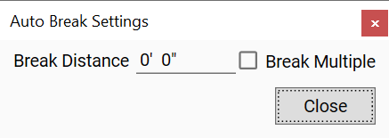
The Auto Break Settings modeless dialog box pops up:

- Type the distance in project units.
- Select a single segment (1) or multiple segments (2) to Auto Break:
- Select a single segment in the view with the modeless dialog open.
- The closest connector to the segment user selects determines where the Auto Break feature begins.
- Check the Break Multiple option to select multiple segments in the view with the modeless dialog open.
- Click the Finish button in the Options Bar to complete the selection.

- Click the end of one of the segments to determine where the Auto Break feature begins.
The nearest connector/end is where the spacing starts and the other end is left with the remainder. A union is placed at every break point as defined.
Notes:
- The unit of measurement for Length will follow the settings for project units. (i.e. If the project units are in mm the Select Distance will read in mm.)
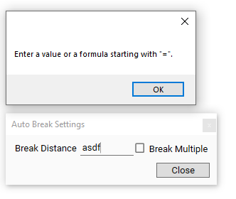
- The Break Distance will remind the user to re-type if the value is invalid, such as "asdf".

- The Break Distance can also be considered the 'Cut Length' which indicates the length of each segment after breaking MEP runs, excluding the union length.
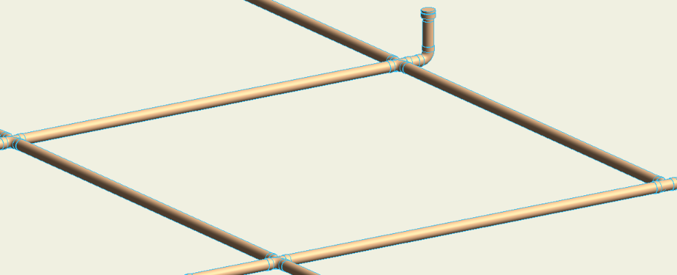
Example before Auto Break:

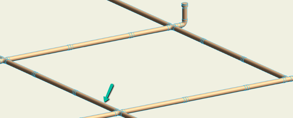
Example after Auto Break, where the green arrow indicates the selected determining starting side for each of the multiple selected segments:
